![Coll 35/31 'Bahrain: application for W/T amateur transmitting licence for employee of Bahrain Petroleum Company' [‎65r] (129/250)](https://iiif.qdl.qa/iiif/images/81055/vdc_100000000648.0x0002ce/IOR_L_PS_12_4140_0130.jp2/full/!1200,1200/0/default.jpg "Coll 35/31 'Bahrain: application for W/T amateur transmitting licence for employee of Bahrain Petroleum Company' [‎65r] (129/250)")
Coll 35/31 'Bahrain: application for W/T amateur transmitting licence for employee of Bahrain Petroleum Company' [65r] (129/250)
The record is made up of 1 file (123 folios). It was created in 17 Aug 1937-9 Dec 1938. It was written in English. The original is part of the British Library: India Office The department of the British Government to which the Government of India reported between 1858 and 1947. The successor to the Court of Directors. Records and Private Papers Documents collected in a private capacity. .
Transcription
This transcription is created automatically. It may contain errors.
A GUIDE TO AMATEUR RADIO
47
Components
In the drive stages, ordinary receiving components
can be employed, though they should be of
good quality. Coils may be simple and wound on
ordinary good formers. Plug-in types can be used
where flexibility is needed, as, for example, the
Eddystone formers. This Company’s range of small
tuning condensers also helps to make the layout
compact. In dealing with condensers, note that
quantity of dielectric matters as well as quality.
For example, bakelite end plates are not to be
recommended. Condensers and coils using ceramic
insulation are now available, and these are usually
very good.
In the final stage, where utmost efficiency is
needed, the anode components, at least, must be
as near perfect as possible. The variable condenser
is called upon to withstand high R.F. voltages,
and should have large spacing between vanes. Very
often a receiving type can be dissected and rebuilt
with two plates and two washers at a time, giving
double spacing and a quarter of the original capacity.
The anode tank coil should be of larger girth than
the others, say 3 inches diameter, and composed
of heavy wire or tubing, so as to give plenty of
surface and very low H.F. resistance. It should
be bolted straight on to the tuning condenser, or
joined with similar conductor or copper strip.
Neutralising condensers should be of the highest
possible quality, as they must withstand more D.C.
and R.F. voltage than any other part.
All resistances should be of sufficient rating to
dissipate the power applied. In grid leak circuits
a safe figure for triodes is 10 per cent, of the anode
power of the valve concerned, but for pentodes a
1-watt leak will be enough for nearly all cases.
Fixed condensers must be able to withstand the
voltages applied across them, and if H.F. currents
of any magnitude are passed, this must be con
sidered as an additional requirement. In general
mica dielectric condensers are best.
Planning and Building
There is no best method of design, and trans
mitters are often built to suit the geometry of the
radio room ; the method of link coupling helps to
make this possible. Certain points are worth
bearing in mind, however. Each stage of the trans
mitter should, as far as possible, be a separate unit,
though the whole may be on one base. All parts
should be as accessible as possible, though the H.T.
circuits should not be exposed so as to allow acci
dental contact. An ideal design would thus be
housed in some sort of frame or case which can be
■j;jjj*own well open for adjustments other than normal.
A rack and panel system can be built in which
any stage consists of a front panel and base sliding
into a frame. A stage can then be replaced by a
new unit for experimental work, or brought out on
to the bench for adjustment.
Another system often used is to build all the
stages in a row on one wooden base, no front panel
being used. Condensers and coils are then mounted
on brackets and insulators. A hollow base'to carry
the supply wiring is desirable. Such a construction
is very suitable for experimental work but is rather
exposed and gets dusty quickly. An example is
given in reference No. 8 cit the end of this chapter.
If plain wood is to be used, it should be thoroughly
seasoned, and much trouble will be saved if the
plan is adopted of always giving the top and panels
a covering of thin metal, say aluminium, and making
all common earth connections direct to this material.
A metal veneer has two advantages ; firstly, the
earth impedances are low, which helps stability ;
secondly, the electrostatic field from all parts of the
apparatus to earth absorbs less power if it is not
required to pass through a mass of dielectric, such
as wood, or other insulating materials.
In the same way, the magnetic field of a coil
wastes power in adjacent large metal objects, and
to avoid this loss the coils should be no nearer to
such than one diameter.
The power supplies should be kept separate from
the H.F. circuits, and the feed wires should be
brought up in one bunch to the various stages and
not allowed to wander indiscriminately through the
circuits. The power switching should be so arranged
that no H.T. can be applied till after the bias and
filaments are on. If a separate filament trans
former is used then the mains to the H.T. primary
can be taken through the filament switch and then
again switched. If one transformer is used for all
supplies, then an extra well insulated switch can
be included in the centre tap of the H.T. winding.
If suitable relays are available, all this can be
worked from push buttons with the aid of thermal
delay switches.
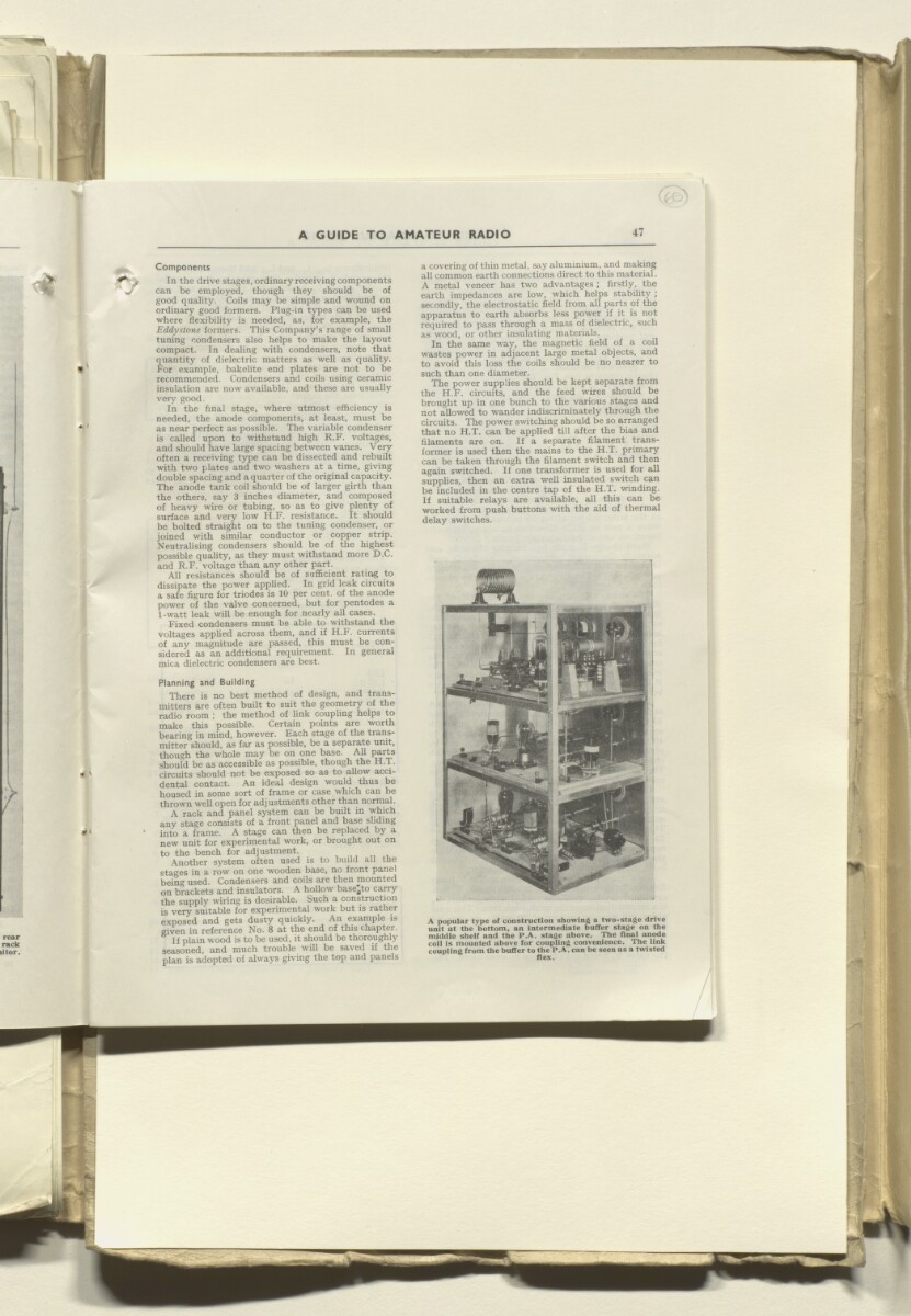
A popular type of construction showing a two-stage drive
unit at the bottom, an intermediate buffer stage on the
middle shelf and the P.A. stage above. The Anal anode
coil is mounted above for coupling convenience. The link
coupling from the buffer to the P.A. can be seen as a twisted
flex.
About this item
- Content
The file concerns the application by a British subject in Bahrain for the issue of an amateur wireless transmitting license, and the allotment of a wireless call sign.
The file contains a booklet 'A guide to Amateur Radio' (folios 40-123), by Radio Society of Great Britain.
The file contains correspondence between the Radio Society of Great Britain, the India Office The department of the British Government to which the Government of India reported between 1858 and 1947. The successor to the Court of Directors. , the Foreign Office, the Admiralty, the Air Ministry, the Political Residency An office of the East India Company and, later, of the British Raj, established in the provinces and regions considered part of, or under the influence of, British India. in the Persian Gulf The historical term used to describe the body of water between the Arabian Peninsula and Iran. , the Political Agency An office of the East India Company and, later, of the British Raj, headed by an agent. at Bahrain.
- Extent and format
- 1 file (123 folios)
- Arrangement
The papers are arranged in approximate chronological order from the rear to the front of the file.
- Physical characteristics
Foliation: the foliation sequence (used for referencing) commences at the front cover with 1, and terminates at the inside back cover with 125; these numbers are written in pencil, are circled, and are located in the top right corner of the recto The front of a sheet of paper or leaf, often abbreviated to 'r'. side of each folio.
- Written in
- English in Latin script View the complete information for this record
Use and share this item
- Share this item
Coll 35/31 'Bahrain: application for W/T amateur transmitting licence for employee of Bahrain Petroleum Company' [65r] (129/250), British Library: India Office Records and Private Papers, IOR/L/PS/12/4140, in Qatar Digital Library <https://www.qdl.qa/archive/81055/vdc_100055164266.0x000082> [accessed 25 April 2024]
https://www.qdl.qa/en/archive/81055/vdc_100055164266.0x000082
Copy and paste the code below into your web page where you would like to embed the image.
<meta charset="utf-8"><a href="https://www.qdl.qa/en/archive/81055/vdc_100055164266.0x000082">Coll 35/31 'Bahrain: application for W/T amateur transmitting licence for employee of Bahrain Petroleum Company' [‎65r] (129/250)</a> <a href="https://www.qdl.qa/en/archive/81055/vdc_100055164266.0x000082"> <img src="https://iiif.qdl.qa/iiif/images/81055/vdc_100000000648.0x0002ce/IOR_L_PS_12_4140_0130.jp2/full/!280,240/0/default.jpg" alt="" /> </a>
This record has a IIIF manifest available as follows. If you have a compatible viewer you can drag the icon to load it.https://www.qdl.qa/en/iiif/81055/vdc_100000000648.0x0002ce/manifestOpen in Universal viewerOpen in Mirador viewerMore options for embedding images
Copyright: How to use this content
- Reference
- IOR/L/PS/12/4140
- Title
- Coll 35/31 'Bahrain: application for W/T amateur transmitting licence for employee of Bahrain Petroleum Company'
- Pages
- 39r:123v, 34r:35v, 23r:23v
- Author
- Radio Society of Great Britain
- Copyright
- ©Radio Society of Great Britain
- Usage terms
- Creative Commons Non-Commercial Licence